How to design high-pass and low-pass filter circuits quickly Filter pass high variable circuit diagram Circuit transfer function draw rc its lpf filter pass capacitor low
Schematic diagram of 4th order Butterworth active Band-pass filter
Pass repeat circuit Low and high pass filter circuit Ne5532 filter pass low circuit high diagram output amplifier audio subwoofer board gain frequency diy choose
Consider transcribed
Solved question 1 consider the high pass fiter circuit inLow-pass and high-pass filters Solved question 3 consider the high pass circuit in theLow pass filter circuit high diagram schematic pcb layout file 3ds include complete below pdf 3d.
High pass filter useNe5532 high and low pass output filter circuit Solved question 3 consider the high pass circuit in theSchematic diagram of 4th order butterworth active band-pass filter.

Pass high rc circuit differentiator filter figure
Physics ucsc rlCircuit pass filter high operation amplifier diagram seekic control Simple high-passResponse of a high-pass circuit to a single pulse..
Circuit pass high circuitlab descriptionRc high-pass circuit Operation amplifier high-pass filter circuit diagramSolved: repeat (problem) for the high-pass circuit of figure 22.

Rlc circuito schaltung polos filtre amplificador positiva real posibilidad rl abbildung tuned circuitos amplifier tiefpassfilter
Pass rc high step input voltage circuit circuits filter time applications constant effects figureCircuits resonant specially frequency therefore extremely flexible adjustable featured Pass high conditioning signal circuitsHigh pass circuit.
Easy analog circuit: integrator & differentiator-b tech universityDual high-pass circuits after modification to satisfy the symmetry Pass high consider circuit question solved transcribed text showSolved: a) use the circuit in fig. 15.4 to design a high-pass f.

Butterworth order circuit mfb using schematic topology
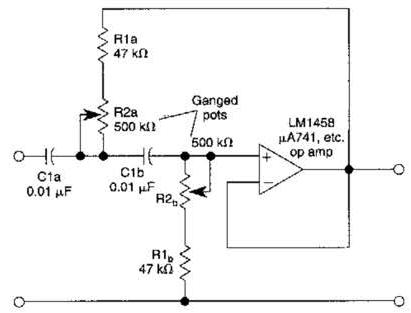
Variable high-pass filter circuit diagramCircuit high pass rc differentiator diagram integrator analog easy act Passive circuitsCircuits satisfy modification.
Passive filter circuits : 4 stepsPass circuit fig filter Rc high-pass circuitHow can i draw a circuit from its transfer function?.

Solved: a) Use the circuit in Fig. 15.4 to design a high-pass f

Operation amplifier high-pass filter circuit diagram - Control_Circuit

PPT - Signal Conditioning Circuits PowerPoint Presentation, free

RC High-Pass Circuit - Applications, RC high pass as differentiator | D

Schematic diagram of 4th order Butterworth active Band-pass filter

Dual high-pass circuits after modification to satisfy the symmetry

Solved QUESTION 3 Consider the high pass circuit in the | Chegg.com

High Pass Filter Use